|
|
|
|
|
|
||

|
|
|
|
|
|
|

|
|
|

|
|
|

|
|
|
|
|
||
|
|
|
|

|
|
|

|
|
|

|
|
|
|
|

|
|
|
|
|
|
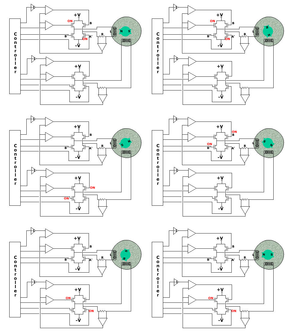
From satellite tracking systems to optical attenuators the applications of the stepper motor are prolific. As with most open loop stepper control systems the operation of these motors is simple in concept but you risk odd behavior if the quirks are not well understood.
The designer of stepper motor systems must take the time to match the controller to the particular characteristics of the chosen motor and the application. Things like heat dissipation, self resonance and half/full step operation all effect the way the motor is controlled. Many chip manufactures offer off the shelf controllers for these motors but it is very simple to roll your own in the form of a small PLD circuit. Depending on the number of required features it may be cost effective to buy the driver chip. In any case the high power bridge stage will typically be separate from the control chip so the designer must pay attention to cross-conduction, power dissipation and electrical noise issues.
Basic operation consists of sequentially energizing a set of coils to rotate the motor shaft. The polarity of the coil current and the sequence order determines the direction of shaft rotation. The speed of coil current changes limit the motor speed. From an electrical point of view, the issue becomes driving current through a coil, by following V=L(di/dt) the higher the drive voltage the quicker the current can change. By using a constant current driver the drive electronics apply maximum V at the start of each sequence then back off the voltage as the current reaches a steady state value. The steady state current is an important parameter in that it will effect the motor heating, hold power, and self resonance speed.
